Three-dimensional OpenGL display of the current data window can be invoked with the button with symbol of cube in View button row of main window.
This feature is optional, i.e. it can be disabled at compile time. It can also happen that while Gwyddion is capable of 3D data display your system does not support it. In both cases an attempt to invoke 3D view gives an error message explaining which of the two cases occurred. In the former case you have to ask the producers of Gwyddion executables to build them with 3D support or build Gwyddion yourself from source code. If it is the latter case, refer to your operating system guide on how to enable OpenGL 3D capabilities. If you experience a poor performance of the 3D view in MS Windows try disabling desktop composition for Gwyddion (in Compatibility tab of the Gwyddion shortcut).
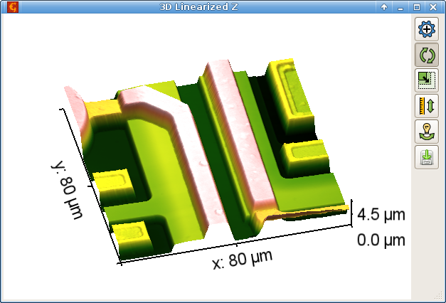
The 3D window has two possible forms: with basic and expanded controls. It starts with basic controls only, this form is displayed on the following figure. It can be switched to the expanded form (and back) with an expander button in the upper right corner. Clicking on the view with right mouse button brings a quick colour gradient/GL material selector.
Basic 3D window contains interaction mode controls at the right side of the view. By default, dragging the view with mouse rotates it horizontally and vertically. All possible modes are listed below, together with hotkeys that switch between them:
-
Rotation
(R)

The default when the 3D view is newly displayed. Dragging the view horizontally rotates it around z-axis, vertical drag rotates it around horizontal axis parallel with the plane of view.
-
Scaling
(S)

Dragging the view upwards enlarges it; dragging in downwards makes it smaller. The size can be also adjusted using the mouse scroll wheel.
-
Z-scaling
(V – value scale)

Dragging the view upwards increases the z-scale, making the hills and valleys more pronounced. Dragging it downwards decreases the value scale. The value scale can be also adjusted using the mouse scroll wheel with Shift pressed.
-
Light rotation
(L)

This control is available when there the visualization mode has a light source, i.e. in lighting and overlay modes. Dragging the view changes position of the light source similarly to rotation of data in normal rotation mode. Horizontal movement changes the φ angle (direction in the horizontal plane). Vertical movement changes the ϑ angle between the light direction and the horizontal plane. The light position is visualised using a “wheel” around the surface.
The basic controls also include an image export button.
In expanded controls the mode buttons are located in top row, however their function does not change. In addition, there are several tabs with options below them:
- Basic – controls to set rotations, scales and axis line width numerically and to switch on and off axes, axis labels, perspective projection and display of masked areas.
- Light & Material – visualization settings. This tab also contains controls to set light position numerically.
- Labels – fine tuning of sizes, positions, and other properties of axis labels.
- Colourbar – settings for the false colour bar which can be displayed on the right side of the 3D view.
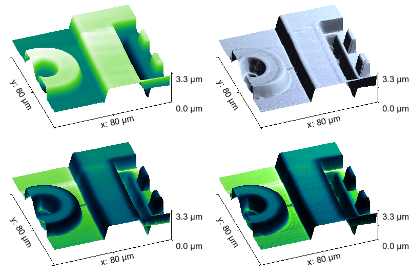
Gwyddion 3D view has several visualization modes, selected in Light & Material, that combine two basic methods:
- False colour representation of data values, similar to normal image view.
- Rendering illumination of the surface with a light source (defined by the light controls).
Modes Gradient and Overlay – no light do not use illumination. The only difference between them is that in the simple gradient mode the colours always corresponds to the heights; in the overlay mode different images can be used for heights and colours. In Lighting mode the surface illumination is rendered using the selected material. Finally, Overlay combines colouring and lighting. Again, heights and colours can be given by different images.
The 3D view can be saved into a bitmap image using the button. The image has exactly the same size and contents as displayed on the screen – except for possible removal of empty borders, if enabled with Autocrop in the Basic tab.
The default image format is PNG (Portable Network Graphics). By changing
the file extension to
.jpg,
.jpeg,
.tif or
.tiff
you can change the image format to JPEG or TIFF.
Entering an unrecognised extension will save a PNG image, albeit with
a confusing extension.
Note due to the peculiarities of certain operating systems, graphics drivers and windowing environments, artefacts may sometimes appear on the exported image in parts corresponding to obscured parts of the 3D view. If you encounter this problem, make sure the 3D view is not obscured by other windows during the image export.
OpenGL material editor can be invoked with → . The controls in the material list are the same as in the colour gradient editor list and the material management works identically. The actual editor is of course different. It allows to edit four quantities defining the material:
- ambient colour ka,α (where α = red, green, blue), controlling the reflection of ambient light that is assumed coming uniformly from all directions,
- diffuse colour kd,α, describing the diffuse reflection which is independent on the direction of incident light and whose apparent brightness is independent of the viewing angle,
- specular colour ks,α, controlling the specular reflection with reflected light intensity dependent on the angle between the observing direction and the direction of light that would be reflected by an ideal mirror with the same normal, and
- shininess s, a numeric exponent determining how much the specular reflection resembles an ideal mirror, smaller values mean rougher surfaces, higher values mean smoother surfaces.
If we denote L the normal vector pointing from the observed surface point to the light source, V the normal vector to the observer, N the normal vector to the surface and R the normal vector in the direction of ideal mirror reflection, the observed light intensity in OpenGL lighting model can be expressed as
where Ia,α, Id,α and Is,α are the ambient, diffuse and specular light source intensities, respectively.